

| aftermarket remote unlock |
| 06-22-2026, (Subject: aftermarket remote unlock ) Post: #1 | |||
| |||
| aftermarket remote unlock I liked my first ProStar, it was a Limited that came with a factory keyfob. I miss having that, so I bought a remote unlock system online for less than $30. This is going into an LT625, but most Internationals are probably the same. I can't just wire it in behind the dash somewhere, because everything is J1939 or J1708 bus controlled. I'm going to install it inside the driver's door. Unfortunately, it'll only operate the driver's door, but I'm not too concerned. The remote unit that I bought has two internal SPDT relays, one for lock, one for unlock. The only way that I can think of connecting it, is to the power lock itself. In testing it, I found that the 2 wires running into it get positive on one wire, negative on the second to lock, and vice versa to unlock. I can't think of anyway to connect this without using two more DPDT relays, wired as shown in the picture. Anyone know of any better way of doing this? | |||


| 06-23-2026, (Subject: aftermarket remote unlock ) Post: #2 | |||
| |||
| RE: aftermarket remote unlock What about upstream of the CECU or whatever controller operates the locks? Like at switch level wiring? Or are the switches also multiplexed and more than just a ground or positive signal to the controller? | |||
|
| 06-24-2026, (Subject: aftermarket remote unlock ) Post: #3 | |||
| |||
| RE: aftermarket remote unlock What I would have done... 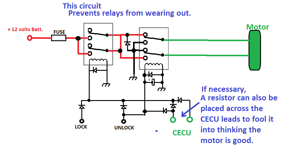 I would want it to last 10+ years...lol. User's Signature: ->: What I post is just my own thoughts and Opinions! --- I AM Full Of S__T!. | |||
|
| 06-25-2026, (Subject: aftermarket remote unlock ) Post: #4 | |||
| |||
| RE: aftermarket remote unlock I'm definitely not an electrical engineer. I understand what you've done there Rawze. I don't understand why or how that makes relays last longer. And, I was hoping to simplify. Nostalgic made me think. Since my remote module only powers internal relays, and doesn't necessarily put out power, maybe I could connect direct to the lock/unlock buttons. I didn't want to risk damaging the driver's side, so I opened the right side. I can't connect into right now, on the road with my 140 watt Weller, and kind of unsure even using a 27 watt pencil at home. Oops, I'm on my phone, not computer. I can't draw in arrows where I'd need to solder to. And yes, I had to remove all 11 T8 torx screws. | |||
| 06-25-2026, (Subject: aftermarket remote unlock ) Post: #5 | |||
| |||
RE: aftermarket remote unlock (06-25-2026 )barf Wrote: I'm definitely not an electrical engineer. I understand what you've done there Rawze. I don't understand why or how that makes relays last longer.... (its my OCD kicking on mostly)... Because any motor/mechanism/coil, solenoid, etc. that has inductive back-emf will cause an arc across the relay contacts every time the power is released, especially if that door mechanism that likely pulls a few to several amps when activated. Depending on how many amps it pulls, this could be a lot of arc-wear on the relays. I have even seen relays contacts burn/wear out when the amperage is only 30-40% of the contact ratings. The diodes (if rated properly) installed will negate any back-emf, causing it be re-routed back into the mechanism instead of arcing across the relays. The relay on the right also has a capacitor as to add a slight delay so that this can happen in the proper direction, no matter the polarity supplied to the mechanism. The capacitor should be sized as to not release the right-most relay until about 0.2-0.4 seconds or so after the first one releases. You need to remember that I was a controls system design engineer for some very, VERY large machinery (hundreds of tons kinda big) that often had hundreds or thousands of inductive load currents across some mighty big relays. Without this type of protections, a relay can arc/flash over and burn out (wear out) the contacts rapidly, or weld them shut. User's Signature: ->: What I post is just my own thoughts and Opinions! --- I AM Full Of S__T!. | |||
|
| 06-26-2026, (Subject: aftermarket remote unlock ) Post: #6 | |||
| |||
| RE: aftermarket remote unlock This diode for relay is also called flyback diode? Most relay boxes or even some relays have built in diodes for the same reasons mentioned. Is there some kind of book that tells concisely about the main design principles and what to look out and also what things should be used to control IGBT and mosfet. | |||
| 06-26-2026, (Subject: aftermarket remote unlock ) Post: #7 | |||
| |||
RE: aftermarket remote unlock (06-26-2026 )mikkhh Wrote: This diode for relay is also called flyback diode? Most relay boxes or even some relays have built in diodes for the same reasons mentioned. not that I know off the top of my head, but DC motor/load back-emf diodes should be sized as follows... (I am a bit rusty these days and this is off the top of my head.. but no, this is not random made up info, its real info)... (rule of thumb math for back-emf diode sizing) === load volts * 2.848 | Max current for back-emf protection = (load current * 0.1675). - I.E.> The Volts rating is not 2x like a lot of ignorant engineers would say that are fresh out of some garbage-arsse schooling. So, A 36volt diode rated 2-amps is typically more than sufficient for most automotive inductive (up to 10-15 amps) loads. This, unless the load was being switched more than 4x a second. Then the rating changes. Another rule of thumb rating used in design with regard to relay/contactor ratings ... For a Relay to have a long-life contact rating on inductive loads, it should be sized, at a minimum, roughly 1.414 times higher than the run load rating. A 10-amp load should have a minimum 15-amp relay running it (plus back-emf protection) for long-life applications. Same thing applies to step up/step down transformers on machinery and AC (Alternating current) loads... random example... A 240-volts AC motor that has a load rating of 30 amps needs .. if it is going to be run off of a 480-volts supply needs a step-down transformer rated for (2.7kva * 1.414) = ... a 10.18kva transformer behind it. Since there are no 10.18 kva transformers readily available, the next size up would be to use a 12kva transformer minimum. Anything less and the transformer is eventually going to get cooked. (laymens version)... The value of 1.414 (or its inverse of 0.707) is one of those rule of thumb 'magic numbers' that is seen throughout electrical design engineering. This is very similar to using 'PI' is used throughout physics. It has to do with Peak power vs rms power. It also has to do with voltage vs current lag in inductive loads at higher power levels too. In the case of DC back-emf off a large coil via a protection diode .. its double due to the forward voltage of supply + the sudden reversal voltage coming back at it due to the collapsing coil (making the voltage 2x larger than the supply) +PLUS+ the voltage leading the current in that coil by roughly 1.414 peak vs rms power ... leading to 2.848 times higher rating for the diode to be fully protected against the negative spike. Its actually 1x + 1.414x (2.414) in actual, but this is still slightly insufficient because of capacitive loading across the substrate of the diode itself... so the rule of thumb of 2.828 is used to cover this, and all other negligible circuit wiring inductance/capacitance, etc. ============ What people do not realize is that if you load up a coil with DC voltage.. it creates this magnetic field all around a coil. - Someone can think of it like a balloon of magnetism being blown up around the coil. When the power is taken away suddenly (say, a relay contract suddenly opening) .. THAT MAGNETIC BALLOON of energy IS GOING SOMEWHERE as it collapses back into the coil windings. .. and the part that no one thinks about is that even if you somehow opened a gap in the relay contacts more than 10+ feet wide at nearly the speed of light ... THAT BACK-EMF voltage/power IS GOING TO JUMP THE GAP (or across the path or least resistance)!!!.. no mater what you do!. It will find its way across something, because otherwise, the resistance goes towards infinity,.. causing the voltage buildup being generated across the coil (in the reverse direction of the supply voltage) is also to go into infinity .. jumping what ever gap, no matter how large, to satisfy this race condition. This is why you always see a 'spark' when a relay contact opens... no matter how fast or hard it opens. That spark causes eats away at the contact metals.. leading to contact pad wear. The only way to prevent it is to re-direct that collapsing energy into some place else. A protection diode does this by shoving the reverse emf back into the coil, creating waves on a pond that dissipate as heat, back into the load instead of jumping across the open contacts. -- With regard to electronic switching,.. like a MOSFET, BGT, transistor, etc.. that protection is far more necessary, as this same 'spark' will jump right across the substrate of the transistor, damaging it and weakening it very fast... causing it to burn out in very short order. Many power-switching transistors have this reverse protection diode built into them, but no all do.. and many that do, are under-rated ... so its not a good idea to rely solely on this. User's Signature: ->: What I post is just my own thoughts and Opinions! --- I AM Full Of S__T!. | |||
| « Next Oldest | Next Newest » |
NOTE: Rawze.com is not affiliated, nor endorses any of the google ads that are displayed on this website.