

| No wiring diagram |
| 10-17-2019, (Subject: No wiring diagram ) Post: #1 | |||
| |||
| No wiring diagram I have a fuse and relay marked “skirt lights”, they are factory wired and labeled. The circuit is not being used for my skirt lights but don’t focus on that just yet. Up here we use an aftermarket program called Mitchell for wiring diagrams. I couldn’t locate it on there, so I went to the dealer. They couldn’t find it in any books either, I believe the online diagrams are basically PDFs of the paper books. I asked one other mechanic about it, and he said you won’t find one, because they were an option. I did get a paper copy of the diagrams and couldn’t find it either. Starting with the basics- pull the relay, using a test light, I have constant power on one terminal. Turn the market light switch to “on”, a second terminal has power. Marker switch off, terminal 2 loses power. Ok, cool. Plug in a relay tester and a relay, turn the switch on. A third terminal now has power. I can hear the click as it does it’s thing. There’s only four pins on this relay, three have brown (power) and one has white (ground). So I’m pretty sure that’s power in, trigger power to operate the relay, and power out. Agreed? So take it a step further, follow the brown wires to the fire wall. There’s a plug on the outside of the firewall. There’s only two brown wires on the inside half, and only one brown wire on the outside half. The one brown wire goes to the factory four wire that feeds the rear junction block for tractor lights. Put everything back together, pulled the plug apart, got a buddy to help for a minute. Back to basics- tested the terminals showing brown wires on the inside for power, using the pins on the outside of the firewall with a test light. I had my buddy pull the fuse in and out while testing, for the skirt light circuit. I could clearly identify with a test light, one pin gaining and loosing power as he removed and inserted the fuse. Does that sound right? I identified the switch that controls power to the relay, confirmed the relay operates, and traced from the inside of the truck to the outside of the firewall to discover which new colour wire to trace on down from there. That’s as far as I had time for. There’s more to the story but I’m trying to not (Lol) overcomplicate things in the first post. Part of this is me thinking this through out loud User's Signature: I have no idea what I’m doing and probably need supervising | |||


| 10-18-2019, (Subject: No wiring diagram ) Post: #2 | |||
| |||
| RE: No wiring diagram what kind of truck or trailer? make/model/year? User's Signature: ->: What I post is just my own thoughts and Opinions! --- I AM Full Of S__T!. | |||
| 10-18-2019, (Subject: No wiring diagram ) Post: #3 | |||
| |||
| RE: No wiring diagram User's Signature: I have no idea what I’m doing and probably need supervising | |||
| 10-18-2019, (Subject: No wiring diagram ) Post: #4 | |||
| |||
| RE: No wiring diagram each of those wires should also be stamped with a number-letter combination. international uses those number-letters to identify circuits, not the wire colors. I am showing fuse F8-E in the panel as the "skirt light" fuse. Is that what u guys came up with? if so... It is wire A54VX (16-gauge brown wire) from the fuse as the +BATT supply line going to pin "A2" on the relay. The white wire u found should be labelled A54-GX (A54-GXB on the relay), and that is the ground wire for the skirt lights on pin "B2" of the relay. A54X and A54XA (also brown wires) are the output of the relay (pin "B1") that supplies the lights themselves. A54XD (also a brown wire) is the control circuit for the relay (relay pin "A1"), and that comes from the body controller itself. -- maybe this helps a bit. User's Signature: ->: What I post is just my own thoughts and Opinions! --- I AM Full Of S__T!. | |||
| 10-18-2019, (Subject: No wiring diagram ) Post: #5 | |||
| |||
RE: No wiring diagram (10-18-2019 )Rawze Wrote: eash of those wires should also be stamped with a number-letter combination. international uses those nomber-letters to identify circuits, not the wire colors. Under the dash all the brown wires were labeled with 58AF or 58AG, 58 was the common number. Outside the firewall it was light grey with no numbers labeled anywhere User's Signature: I have no idea what I’m doing and probably need supervising | |||
| 10-18-2019, (Subject: No wiring diagram ) Post: #6 | |||
| |||
RE: No wiring diagram (10-18-2019 )DDlighttruck Wrote:(10-18-2019 )Rawze Wrote: eash of those wires should also be stamped with a number-letter combination. international uses those nomber-letters to identify circuits, not the wire colors. so, it is a different diagram than the one that i have .. but all is not lost. Just translate the relay pins to the correct wire numbers using the reference above to identify what is what, as it is same circuit, just labelled differently. User's Signature: ->: What I post is just my own thoughts and Opinions! --- I AM Full Of S__T!. | |||
| 10-18-2019, (Subject: No wiring diagram ) Post: #7 | |||
| |||
RE: No wiring diagram (10-18-2019 )Rawze Wrote: each of those wires should also be stamped with a number-letter combination. international uses those number-letters to identify circuits, not the wire colors.I don’t have any “E” fuses at all, my skirt lights fuse is F11-D 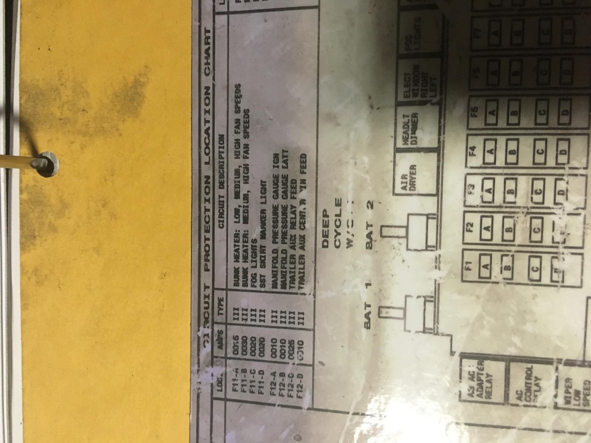 User's Signature: I have no idea what I’m doing and probably need supervising | |||
| 10-18-2019, (Subject: No wiring diagram ) Post: #8 | |||
| |||
RE: No wiring diagram (10-18-2019 )Rawze Wrote:Back to the first question- I followed all the 58 brown wires to the inside firewall plug-(10-18-2019 )DDlighttruck Wrote:(10-18-2019 )Rawze Wrote: eash of those wires should also be stamped with a number-letter combination. international uses those nomber-letters to identify circuits, not the wire colors. If I have a test light on the pin on the outside firewall plug, and I unplug the fuse F11-D, and the test light goes out.... That’s telling me I traced that circuit correctly to the outside firewall...? User's Signature: I have no idea what I’m doing and probably need supervising | |||
| 10-18-2019, (Subject: No wiring diagram ) Post: #9 | |||
| |||
| RE: No wiring diagram if u have the correct fuse, then after unplugging the fuse, one side of the fuse holder will go directly to "A2" on the relay. "B1" on the relay should be going out the firewall to the lights. So what is the actual problem any ways? - you never mentioned what your trying to accomplish. User's Signature: ->: What I post is just my own thoughts and Opinions! --- I AM Full Of S__T!. | |||
| « Next Oldest | Next Newest » |
NOTE: Rawze.com is not affiliated, nor endorses any of the google ads that are displayed on this website.